Link 3D
Description and modeling hypotheses
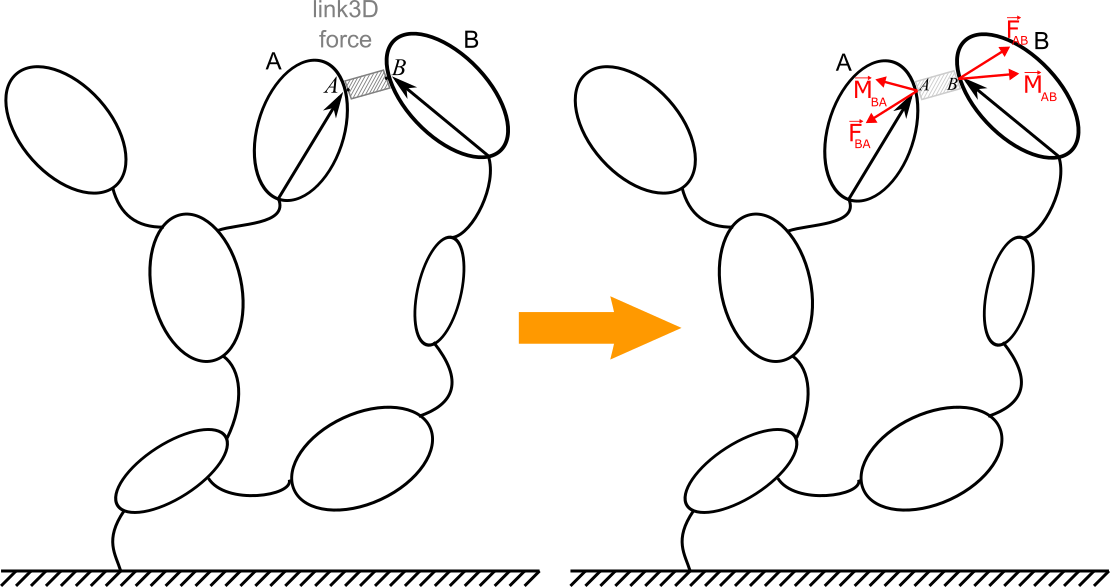
A 3D-link (denoted as link3D in the Robotran computer environment) is used to model an internal 3D force/torque element acting between two bodies A and B of the system. A 3D-link is particularly suited to model the effect of a rubber-type connection (e.g. bushings and silent blocks in a car suspension), a “net of springs” (e.g. in railway bogies), a pneumatic bellow (as in railway carbody suspensions), etc.

Illustration of the 3D link concept using a potato multibody diagram
Unlike the simple link element (link1D), whose force direction must be that of the link (i.e. defined by its two connection points), the 3D-link allows more generally to model three force and three pure torque components induced by the element.
The modeling assumptions underlying 3D-links are as follows:
As for simple links, the mass and inertia of the 3D-link element are assumed to be zero. It allows the application of the Newton action/reaction principle for forces and torques (including moments of forces and pure torques).
Angular deformations of the element must remain limited, ideally in a range that makes acceptable the linearization of the sine and cosine of involved angles, and thus also the linearization of the rotation matrix between bodies A and B. It allows, among other things, to no longer worry about the rotation sequence.
By convention, deformations and deformation velocities (in compression, shearing, bending, torsion, etc.) of the element are established in the frame of the first body A. It is identical for force and pure torque components which result from it.
From these assumptions, two recommendations follow regarding the body frames of the two connected bodies A and B:
For any configurations of the system, they must keep a close orientation (e.g.: modeling a too flexible element is therefore not recommended with a Link3D).
For the reference configuration, they must have their x, y and z axes aligned with (or close to) the directions of main deformations of the element (i.e. tension, shear, bending, torsion), as defined by experimental measurements. The latter will be used for the expression of the constitutive equations of the forces and pure torques (via the user_Link3DForces function).
Robotran implementation
A 3D link is introduced in MBSysPad via the Link menu (see the example below) and by ticking the ‘Link 3D’ box.
The force and pure torque components must be computed in the user_Link3DForces function:
The full relative kinematics between bodies A and B are calculated by the symbolic engine and given as arguments of the user_Link3DForce function. As explained in the function header, they represent the kinematics of the second body B, with respect to the first body A, and expressed in the A body-frame as stated above.
The force and pure torque components returned by the user_LinkForce are expressed in the A body-frame. By convention, only the force and pure torque components with the same sign as the linear and angular deformations (and velocities) will be implemented by the user in the user_Link3DForce function. As for the 1D link element, Robotran will automatically take care of the action/reaction principle of forces and torques in the computer model.
WARNING:
As the force and pure torque components are expressed in the A body-frame, it is necessary to specify the choice of this body A reference. This is done in the Robotran 2D user interface by starting the link on Body A (i.e. by clicking on Body A first) and then putting the link on Body B. This is different from the Link 1D where it does not matter.
Example: a double pendulum-spring-mass system

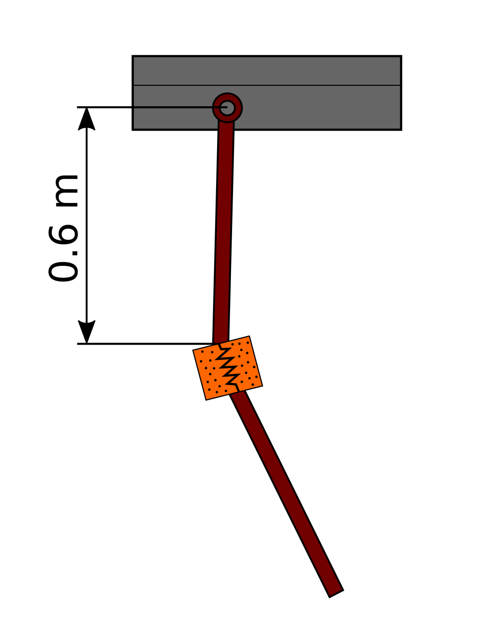
The example model consists of a two bodies linked by a 3D link
REMARK:
In Robotran right handed coordinates convention is used. In this case, on the figure, positive rotations are anticlockwise.
Model data
The example model is composed of the following elements:
Two bodies:
Body 1:
Mass: 5 kg
Inertia along axis \(\hat{I}_{2}\): \(0.1 kg·m^2\)
Anchor point: 0.6 m from the insertion point in the Z direction.
Body 2:
Mass: 5 kg
Inertia along axis \(\hat{I}_{2}\): \(0.1 kg·m^2\)
Joints:
Between the base and body 1:
A revolute joint along axis \(\hat{I}_{2}\) (R2) with a rotational viscous coefficient of 100 Ns/rad.
Between the base and body 2:
A prismatic joint along axis \(\hat{I}_{3}\) (T3)
A prismatic joint along axis \(\hat{I}_{1}\) (T1)
A revolute joint along axis \(\hat{I}_{2}\) (R2)
A 3D spring-damper element:
Force properties along the axis 1 of body 1 frame:
Stiffness: \(10^3\) N/m
Damping: 10 Ns/m
Neutral length: 0 m
Force properties along the axis 3 of body 1 frame:
Stiffness: \(10^3\) N/m
Damping: 10 Ns/m
Neutral length: 0.20 m
Moment properties along the axis 3 of body 1 frame:
Stiffness: \(10^3\) N/rad
Damping: \(10^2\) Ns/rad
Neutral angle: 0 rad
Geometrical data are given in the figure above.
The following initial conditions are considered:
Rotation of body 1 (R2 between the base and body 1): 0.25 rad
Vertical translation of body 2 with respect to the base (T3 between the base and body 2): 0.7 m
Lateral translation of body 2 with respect to the base (T1 between the base and body 2): 0.7 m
Rotation of body 2 with respect to the base (R2 between the base and body 2): 0.0 rad
Step 1: Draw your multibody system
Create a new project
Draw a base body
Body 1:
Insert a R2 joint
Draw body 1
Insert an anchor point
Body 2:
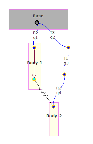
Insert a T3, T1 & R2 joints from the base
Draw body 2
Link 3D :
Insert a 3D link between the bottom of body 1 and the top of body 2
Select the link and activate the option Link3D

Illustration of the example in MBsysPad
Step 2: Generate your multibody equations
Step 3: Write your user function
REMARK:
A joint force/torque is a force/torque acting along the axis of a joint. It is thus:
a force for a prismatic joint,
a torque for revolute joint.
Joint forces correspond to the Qq vector in the equations of motion:
\(\begin{matrix} M(q)\ddot{q} + c(q, \dot{q}, frc, trq, g) = Q(q, \dot{q}) + J^T\lambda \\ h(q) = 0 \end{matrix}\)
Qq is the force/torque acting from the parent body to the child body. The reaction is automatically taken into account by the multibody formalism.
Step 4: Run your simulation
Follow the instructions in Bodies and joints section to run your simulation.
