Sensors
Sensors are used to compute the kinematics of a point of the system. They can compute the following information for a given point:
The absolute position vector
The absolute rotation matrix of the body on which the point is attached
The absolute velocity vector
The absolute angular velocity vector of the body
The absolute acceleration
The absolute angular acceleration vector of the body
The Jacobian matrix of the sensor, i.e. the relation between generalized velocities and the sensor velocity and angular velocity
There are two kinds of sensors:
S sensor: sensor attached to a given point;
F sensor: sensor used to compute external force (see the external force);
Note that there also exist Gen sensor: it is equivalent to S sensors attached on each joint of the system.
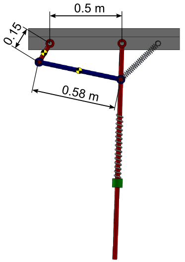
Back to the pendulum-spring example
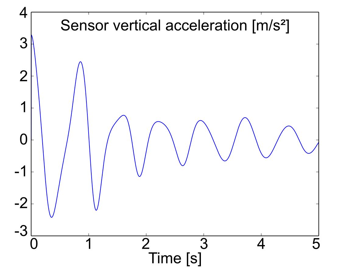
The goal is to capture the vertical acceleration of the point located at the middle of the blue rod.
Position of the sensor
Step 1: Draw your multibody system
Open the existing *.mbs file project with MBsysPad:
Set back the pendulum joint to independent and the crank joint to dependent;
Add an anchor point on the rod and enter its coordinates;
Add a sensor to the anchor point:
Click on the Sensor button;
Click on the anchor point at the end of the rod;
A “S” is added next to the anchor point;
Click on the “S” to edit its properties and give it a name;
Step 2: Generate your multibody equations
Regenerate the multibody equations with the same options as previously.
Step 3: Write your user function
Edit the user_DrivenJoints function to remove the imposed trajectory of the crank. You can delete or comment the part which imposes the trajectory of the crank.
WARNING:
Imposing the trajectory of an independent or dependent joint will lead to inconsistent results.
In matlab there are 2 options in order to store the result of a sensor:
During the simulation in the user_DirDyn_io function, this is similar to saving a custom quantity;
After the simulation, during the post-process.
For both option the acceleration is accessible via the MBS_user.resdirdyn structure:
MBS_user.resdirdyn.tsim: the time
MBS_user.resdirdyn.rodAccZ: the value of the acceleration at the correspondig time
Option 1: on-line sensor calculation
Open the user_dirDyn_io function:
In the ‘init’ case (“process starting”), initialize the result vectors.
In the ‘else’ part (“process running”), calculate the sensor kinematics using the mbs_comp_S_sensor function and save the desired value.
function [] = user_DirDyn_io(mbs_data,tsim,step,flag)
    %...

    if (nargin > 3)         %   process starting
        switch flag
            case 'init'     % initialization of the vectors
                MBS_user.resdirdyn.tsim = zeros(step,1);
                MBS_user.resdirdyn.rodAccZ = zeros(step,1);
            otherwise       %   unused
                ;
        end

    else                    %   process running
        MBS_user.resdirdyn.tsim(step) = tsim;
        id = mbs_get_S_sensor_id(MBS_info, 'RodSensor');
        rodSens = mbs_comp_S_sensor(mbs_data,tsim,id);
        MBS_user.resdirdyn.rodAccZ(step) = rodSens.A(3);
    end

    %...
REMARK:
The calculation of sensor kinematics can be done in any user function if it is useful for defining the constitutive law.
Option 2: post-process calculation
In the main script, after the direct dynamics, add a for loop for calculating the sensor kinematics for each time step of the solution:
%...

%% 2. Direct dynamics [mbs_exe_dirdyn]
[mbs_dirdyn,mbs_data] = mbs_exe_dirdyn(mbs_data,opt.dirdyn);

%% Sensor calculation
MBS_user.resdirdyn.rodAccZ = zeros(length(mbs_dirdyn.tsim),1);
sensId = mbs_get_S_sensor_id(MBS_info, 'RodSensor');

for i=1:length(mbs_dirdyn.tsim)
    % Restoring the state at time i
    t = mbs_dirdyn.tsim(i);
    mbs_data.q = mbs_dirdyn.q(i,:);
    mbs_data.qd = mbs_dirdyn.qd(i,:);
    mbs_data.qdd = mbs_dirdyn.qdd(i,:);

    % Calculate the sensor and save the acceleration at time i
    [rodSens] = mbs_comp_S_sensor(mbs_data,t,sensId);
    MBS_user.resdirdyn.rodAccZ(i) = rodSens.A(3);
end

%...