Insert submodel
The Insert submodel tool is a useful option in MBsysPad when, due to the complexity of the model, we prefer to work in submodels separately and then assembly them in a main model.
Example: Five Point Suspension front model
For the following example, you can use the model Five Point Suspension available in the Robotran website. You will create a main model and you will have to insert the submodels.
Step 1: Create the “main model”
The main model is composed of the following elements:
The Base
6 Joints in the following order from the base: T1-T2-T3-R3-R1-R2
One body Chassis
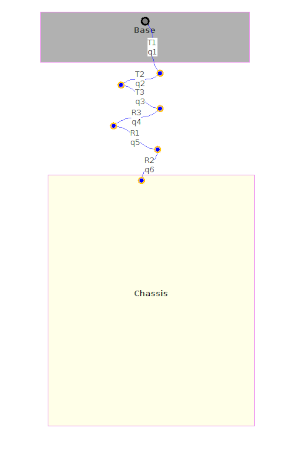
Main model
See the section Bodies and joints to review how to create a model in MBsysPad.
Step 2: Open and modify the submodel
Here you will use the example Five Point Suspension and you will modify it and adapt it before being inserted to the main model:
Install examples from Robotran (clock on the menu Settings > Install Examples)
Open your *.mbs file in MBsysPad
Delete the following elements:
The Poster body
The joint T3 attached to the Poster body
The anchor point of the base
The base
The joint T3 attached to the Chassis body
Attach the Chassis body to the base
Click the base point and drag it to locate approximately the base at the previous Chassis position
Click on the Chassis body
Drag the grey square of the Chassis body and put it on the grey point of the base
Save the model in the project:
Click on the menu File > Save As
In the same directory as the main model, save your new submodel
Step 3: insert the front-left submodel
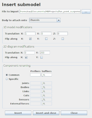
Click on the menu Tools > Insert submodel.
Select your submodel in File to import option.
In Body to attach onto option select Chassis.
In 3D model modifications:
Transation X: 1. The physical model will be introduced at a distance of 1 m from the Chassis.
Check the option Flip along Y. The model will be mirrored along the Y axis to be introduced on the left side of the 3D physical model.
In 2D diagram modifications:
Translation Y: 200. The position of the submodel will be modified in the Y direction only in the MBsysPad, but the real coordinates of the model won’t be modified.
Check the option Flip along X. The model will be placed on the left side of the Chassis in MBsysPad, but its real coordinates won’t be modified.
In Component renaming:
Check Common to modify the suffixes of all elements.
Introduce _FL to add the suffix that will differentiate the elements of the front-left suspension from the rest of the model.
REMARK:
Remember to save periodically so as not to lose information. If you have a problem with the insertion of the submodel you can get your last saved copy back by clicking on the menu File > Reload Project.
Step 4: insert the front-right submodel
Click on the menu Tools > Insert submodel
Select your submodel in File to import option
In Body to attach onto option select Chassis
In 3D model modifications:
Transation X: 1. The physical model will be introduced at a distance +1 m from the Chassis.
In 2D diagram modifications:
Translation Y: 200. The position of the submodel will be modified in the Y direction only in the MBsysPad, but the real coordinates of the model won’t be modified.
In Component renaming:
Check Common option to modify the suffixes of all elements.
Introduce _RL to add the suffix that will differentiate the elements of the front-right suspension from the rest of the model.
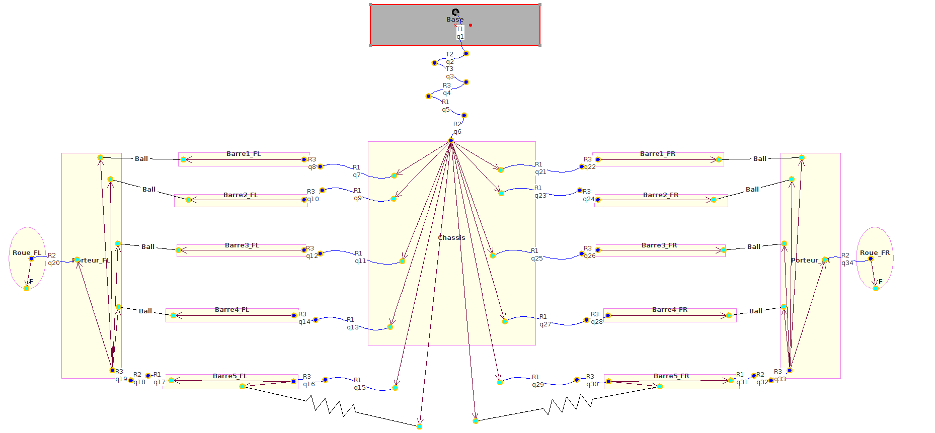
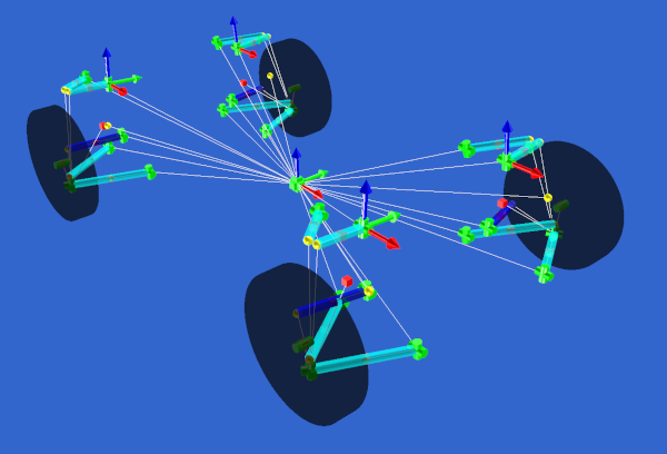
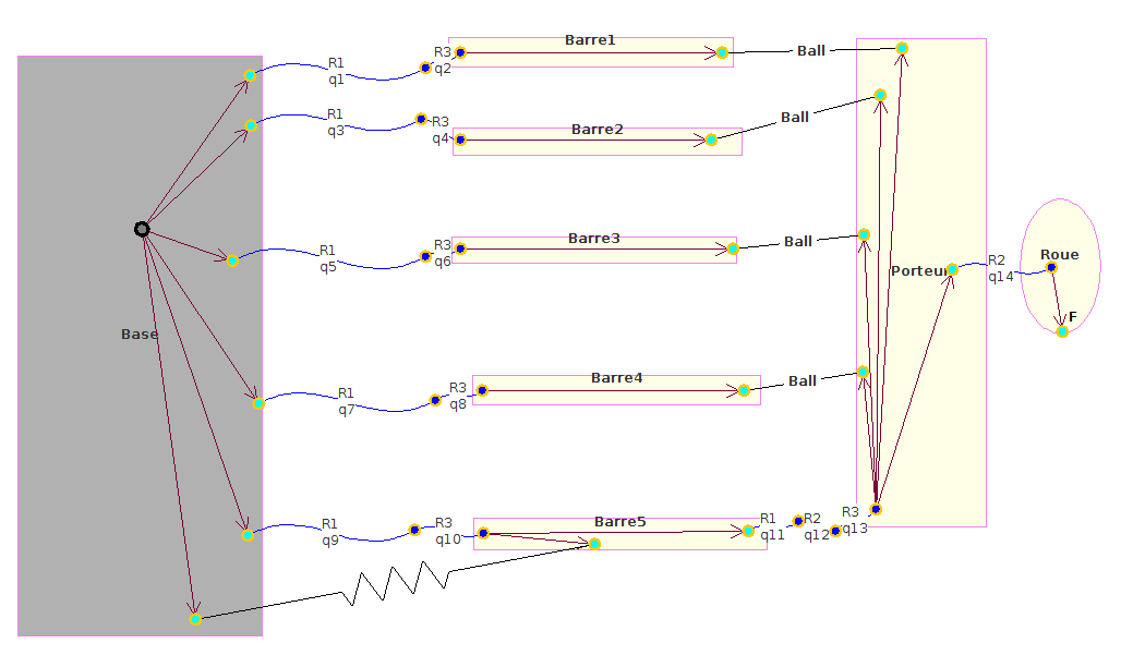
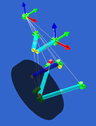
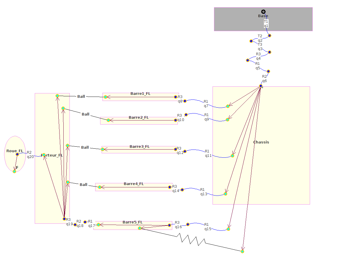
Front 2D diagram
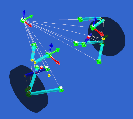
Front 3D model