Tips and tricks
User models
Instead of assigning parameter in the code, parameters values can be introduced via “User Model” in MBsysPad.
Back to the spring-pendulum example
The goal is to store the parameters of the model in the “User Model” and retrieving them in the user function.
REMARK:
Step 4 and 5 are not impacted by theses function. See the Bodies and joints part for more information
Step 1: Draw your multibody system
In MBsysPad, click on “User Model” (under the joint button)
Click the upper “Add” button to add a new user model
Give a name to the user model
Add 3 parameters for the spring (K, C, L0)
Click the lower “Add” button to add a parameter
In the right part of the window, give a name and a value to the parameter
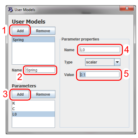
User model gui illustration
WARNING:
Press enter when modifying a parameter value to ensure that the change is correctly taken into account.
REMARK:
User model only serves for storing data. If nothing else is done, they do not modify the behaviour of the system. They must be accessed in user functions to be taken into account.
Generate the user models C files
The user models are not loaded with the *.mbs file. They need to be generated before compiling your model. The generation is done in the MBSysPad interface, open your project and click on Tools->Generate C-specific user files. You have to save your project before the generation, otherwise your current modifications will not be included.
WARNING:
For this step you must have compiled the User file generation application. Please refer to the installation instructions. See for instance here for Windows.
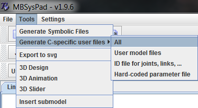
Generation of the user models
This action should create in your userfctR/ folder of your project the following files:
user_model.h
user_model.c
user_all_id.h
Step 2: Generate your multibody equations
It is not necessary to regenerate the multibody equations after a modification or a creation of user models since the symbolic files are not affected by user models. However, you may need to re-generate the project with CMake to take into account the newly generated user model files.
REMARK:
When modifying a user model parameter in MBsysPad, you must save the model in MBsysPad and reload the model in your code so that the modification take effect.
Step 3: Write your user function
The parameters defined in MBsysPad can then be accessed via the mbs data structure in the code.
Edit the user_JointForces function (open the file from the userfctR subfolder of your project);
Modify the spring-damper law to get the parameter values from the user model:
The file user_model.h is now included.
The attribution of K, C and L0 use
mbs_data->user_model->Spring.PARAMto retrieve the value of the parameter defined in MBsysPad.
//...
#include "user_model.h"
//...

double* user_JointForces(MbsData *mbs_data, double tsim)
{
    //...
    // set the joint force in joint 2
    int id = 2;

    UserModel *um = mbs_data->user_model;
    double K = um->Spring.K;
    double C = um->Spring.C;
    double L0 = um->Spring.L0;

    mbs_data->Qq[id] = - ( K*(mbs_data->q[id]-L0) + C*mbs_data->qd[id] );
    //...
}
REMARK:
Advanced use of User Models (creation of a custom structure in C) can be found in this tutorial Structures
Get the ID of a specific joint / body / link / “F sensor” / “S sensor”
Instead of hardcoding the joint index in user functions, it is possible to get the joint (or another element) index on basis of its name using MBsysLab functions.
REMARK:
Joint numbering in MBsysPad may be modified when modifying the tree structure of the system. Since the user has no full control on the joint numbering, using function to retrieve the ID make the code more robust with respect to topology modifications.
Only the function to retrieve a joint ID is illustrated, see the end of the section for the equivalent function.
Back to the spring-pendulum example
The model defined in the Bodies and joints section is used to illustrate this feature. The goal is to Get the slider joint id via a function in the user_JointForce function.
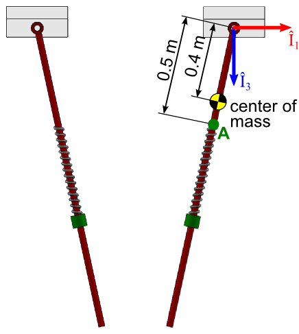
Pendulum spring illustration
REMARK:
Step 2, 4 and 5 are not impacted by theses function. See the Bodies and joints part for more information.
Step 1: Draw your multibody system
Open the existing *.mbs file project with MBsysPad.
Select the T3 joint (q2)
Give an explicit name to the joint (in this example: “Spring_Slider”)
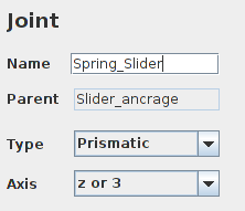
Joint name illustration
Save your project.
Generate the user models C files
The user models are not loaded with the *.mbs file. They need to be generated before compiling your model. The generation is done in the MBSysPad interface, open your project and click on Tools->Generate C-specific user files. See also Here above
Generation of the user ID
Step 3: Write your user function
Edit the user_JointForces function (open the file from the userfctR subfolder of your project);
Modify the spring-damper law to get id of the joint by its name:
The file user_all_id.h is now included.
Look at the int id =… line.
//...
#include "user_all_id.h"
//...

double* user_JointForces(MbsData *mbs_data, double tsim)
{
    //...
    // set the joint force in joint named 'Spring_Slider'
    int id = Spring_Slider_id;
    UserModel *um = mbs_data->user_model;
    double K = um->Spring.K;
    double C = um->Spring.C;
    double L0 = um->Spring.L0;

    mbs_data->Qq[id] = - ( K*(mbs_data->q[id]-L0) + C*mbs_data->qd[id] );
    //...
}
VERSION EVOLUTION:
In previous version you needed to add 1 to the joint id retrieved. It’s no more needed.
Equivalent function for other element
To retrieve any element id from its name, just:
include user_all_id.h in the file
add _id after the element’s name: name_id
Initial conditions
The initial condition previously defined in MBsysPad can also be defined in the code after project loading.
REMARK:
Step 1, 2, 3 and 5 are not impacted by theses modifications.
Back to the spring-pendulum example
The goal is to modify in the main script the initial rotation and rotational speed of the pendulum.
Step 4: Run your simulation
Edit the main function and add the following command
After the project loading (load() function)
Before the coordinate partitioning (mbs_new_part function) and time integration (mbs_new_dirdyn function)
//...

// Define the initial condition of the joint 1 (rotation of the pendulum)
int Joint_ID = 1;

mbs_data->q[Joint_ID] = 0.2;
// The initial rotation of the pendulum is set to 0.2 rad

mbs_data->qd[Joint_ID] = 0.01;
// The initial angular velocity of the pendulum is set to 0.01 rad/s

//...
REMARK:
The initial conditions are stored in the mbs_data->q0, ->qd0 and ->qdd0 vectors at the loading of the .mbs file. If you need to access to q0 (or qd0 or qdd0) during the computation you need to update these values aswell.
REMARK:
If you change the value of an independent joint involved in a kinematic loop, you can fail to close the loop (max Newton-Raphson iteration reached).
If you change the value of a dependent joint, you only change the initial configuration of the Newton-Raphson iteration.
MBsysPad 2D diagram manipulation
Moving several elements at once
Press the SHIFT key to move a component and all its descendence. Moving the base while pressing SHIFT will move all the drawing.
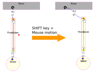
Moving a component and all its descendence
Modifying the attach point of a body, joint, anchor point, sensor…
Select the element (body, joint, anchor point, sensor…) you want to modify. A small grey square appears next to the attach point of your element. Click on it (and keep the button pressed) and move the the mouse to the desired attach point.
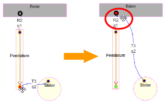
Modifying the attach point of a body, joint, anchor point, sensor
REMARK:
The attach point is colored in red while moving the mouse. Check that you have reached the desired location.
Saving a custom quantity
It is often useful to get the time history of a custom variable which is not contained by default in the result structure returned by the direct dynamics module. The variables contained by default are:
The position, velocity and acceleration of each joint at each time step
The state vectors at each time step (see User derivatives if you don’t know what are state vectors)
The way to save custom quantity highly differs between the codes (Matlab, python, C).
MBsysC and Python, in the opposite of Matlab version, also save the following value by default:
All values of links forces (z, zd, force value)
All joints force/torque value
All force/torque required in the driven joints
MBsysC offers to save several type of value:
A single value:
set_output(double value, char* label);A vector of values:
In
user_dirdyn_initfunction, declare the vector size and name with the function:define_output_vector(char* label, int size)Fill the vector in any of your user function or in the
user_dirdyn_loopfunction with:A specific vector:
set_output_vector(double *v_ptr, char* label)Multiple values composing the vector:
set_output_value(double value, int index, char* label)
By default we allow the user to save up to 12 single value
(set_output() function), if you need more output value update the
field max_save_user in the MbsDirdynOptions structure.
More details can be found in the MBsysC documentation.
Back to the spring-pendulum example
The goal is to store the spring force and the damper force of the link.
REMARK:
Step 1, 2, 4 and 5 are not impacted by theses modifications.
Step 3: Write your user function
Edit the user_LinkForces function (open the file from the userfctR subfolder of your project) and:
Include set_output.h
Add the call to the set_output function
//...
#include "set_output.h"
//...
double user_LinkForces(double Z, double Zd, MbsData *mbs_data, double tsim, int ilnk)
{
    double Flink = 0;

    switch(ilnk)
    {
        // get the link id
        case MyLink_id :
        {
            // retrieve the user model
            UserModel *um = mbs_data->user_model;
            double K  = um->mylink.K;
            double C  = um->mylink.C;
            double Z0 = um->mylink.L0;

            Flink = K*(Z-Z0)+C*Zd;

            // Save the spring and damper forces
            set_output(K*(Z-Z0), "Fspring");
            set_output(C*Zd, "Fdamper");

            break;
        }
    }

    return  Flink;
}
The results will be saved in the resultR/ folder.
Integrator
Integrator type
MBsysC come with different integrators (RK4, Dopri5…), the selection
of the integrator is done by setting
mbs_dirdyn->options->integrator to the wanted value. You need to
add #include "integrator.h" at the top of the file. The list of
the available integrators is in the MBsysC
documentation.
For a more complete description of additional features of Robotran in C, see this tutorial.
Force the integrator to pass at specific time value
If you need an adaptive integrator to pass at some fixed time stepped
value (for example to synchronization), you can activate the
flag_waypoint in the MbsDirdynOptions structure. Then the step
size is defined in the delta_t_wp field.