Driven variables
Driven variables are joints for which the trajectory is imposed by the user. Their position, velocity and acceleration must be given as a function of time.
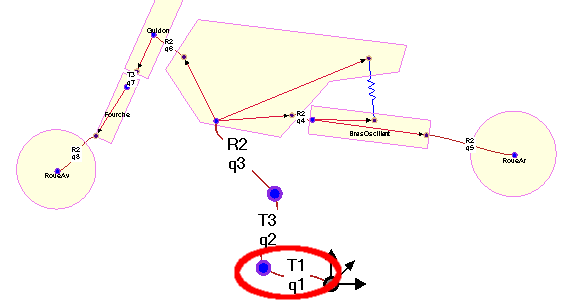
Illustration of a mbsyspad diagram with an imposed dof
Back to the pendulum-spring example
Impose a constant clockwise rotation speed of the crank with a frequency of 0.5Hz.
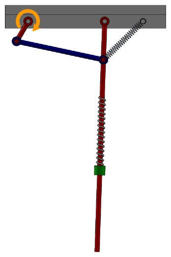
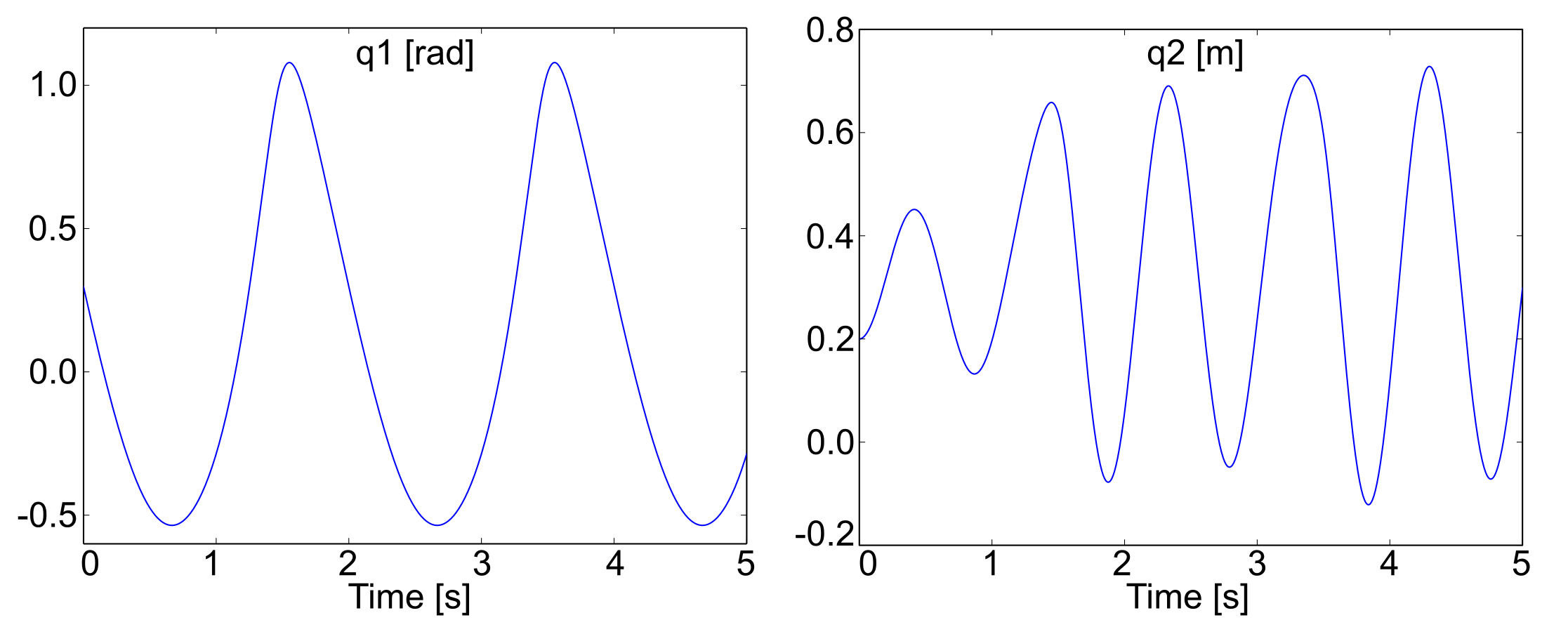
Pendulum spring illustration with driven variable
REMARK:
Step 2, 4 and 5 are not impacted by theses function. See the Bodies and joints part for more information
Step 1: Draw your multibody system
Open the PendulumSpring model in MBsysPad
Set the nature of the crank joint to Forced-Driven
Click on the joint to edit its properties
Click on Driven
Remark: in the step 2 we assume that the name of the joint is
R2_crank. Adapt either the name in MBsysPad or in the code.
Set the nature of the pendulum joint to dependent to maintain the correct number of dependent variables
If you had modified the joint nature in the code in the previous section you have to update the code, modifications done in MBsysPad are overwritten.
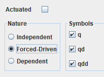
Snapshot of the nature section of the joint properties gui
REMARK:
Setting the joint nature can also be done in the code. This feature is only recommended for advanced users because any change of joint nature done in MBsysPad will be overwritten by the code!
Check the mbs_set_qdriven function to do it in the code.
Step 3: Write your user function
Edit the user_DrivenJoints function (open the file from the userfctR subfolder of your project)
include the user ID header in the preprocessing directive;
See the links section to generate the ID.
Write the trajectory equations:
Note : The initial position of the crank (set in MBsysPad) will be overwritten by the command
mbs_data->q[id] = omega*tsim;. You can retrieve the initial position withmbs_data->q0[id]and put this value in your function.
//...
#include "user_all_id.h"
//...

void user_DrivenJoints(MbsData *mbs_data,double tsim)
{
   //...

   // get the joint id
   int id = R2_crank_id;
   double omega = -2.0*M_PI*0.5;

   // impose the position, velocity and acceleration
   mbs_data->q[id] = omega*tsim;
   mbs_data->qd[id] = omega;
   mbs_data->qdd[id] = 0;

   //...
}
The MBsysC source code define functions that compute some basic trajectories (cosine, ramp, …) and the possibility to combine them (add, multiply…). The functions computes the position, velocity and acceleration resulting of the choosen trajectory. All the function are listed in the documentation.
VERSION EVOLUTION:
In previous version you needed to add 1 to the id retrieved. It’s no more needed.
REMARK:
You have to set the full trajectory: position, velocity and acceleration. The component you don’t set will not be updated during the simulation.
For example in the spring pendulum: If you set the velocity only, the mass will oscillate (due to the velocity) but the crank will not rotate (the position will always be the initial position).