External forces
The external forces are used to impose a solicitation from the environment on to the system:
The solicitation consists of applying an external force and/or an external torque on the body;
The three components of the force and/or torque must be calculated by the user in the user_ExtForces function;
The application point is defined in MBsysPad and its kinematics is provided in the input of the user_ExtForces;
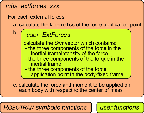
The user_ExtForces function must return:
the 3 components of the force in the inertial frame;
the 3 components of the torque in the inertial frame;
the 3 components of the application point in the body fixed frame, which allows to modify the position where the force is applied;
Each external force is associated with a “F sensor” which give the kinematics of the application point;

Flow chart of the function call for computing external forces
Back to the pendulum-spring example
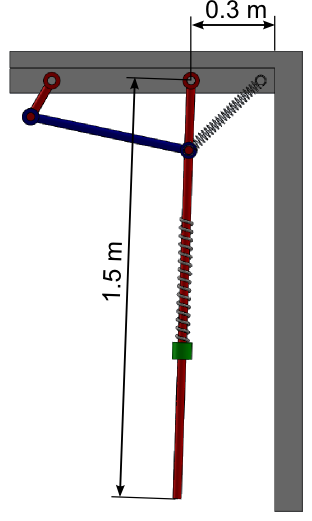
The goal is to add a wall next to the pendulum with the following assumptions:
The end of the pendulum hits the wall;
The thickness of the pendulum is neglected;
The wall is modelled as a spring in the horizontal direction with a stiffness K = 10 kN/m.

Schematic representation of the new system
REMARK:
Step 2, 4 and 5 are not impacted by theses modifications.
Step 1: Draw your multibody system
Open the Pendulum Spring model in MBsysPad;
Add an anchor on the pendulum;
Enter the coordinates to locate the point at the end of the pendulum;
Add the external force:
Click on the ExtForce button;
Click on the anchor point at the end of the pendulum;
A “F” is added next to the anchor point;
Click on the “F” to edit its properties and give it a name;
Step 2: Generate your multibody equations
You have to generate the multibody equations after the creation of an external force. You also need to regenerate the user models files.
Step 3: Write your user function
Edit the user_ExtForces function (open the file from the userfctR subfolder of your project) and write the force equations.
You have to include user_all_id.h;
You have to declare the variable outside the switch-case;
//...
#include "user_all_id.h"
//...
double* user_ExtForces(double PxF[4], double RxF[4][4],
                       double VxF[4], double OMxF[4],
                       double AxF[4], double OMPxF[4],
                       MbsData *mbs_data, double tsim,int ixF)
{
    //...

    /* Begin of user declaration */
    double gap, K;
    /* End of user declaration */

    //...

    switch(ixF)
    {
    /* Begin of user code */

        case LateralBumpstop_id:
            gap = 0.3;
            K = 10000;
            if (PxF[1]>gap)
            {
                Fx = -K * (PxF[1] - gap);
            }
            break;

    /* End of user code */
    }

    //...
    return Swr
REMARK:
By default, the dxF components to the position of the anchor point defined in MBsysPad using the following commands (see the first commands of the user_ExtForces function):
idpt = mbs_data->xfidpt[ixF];
dxF[1] = mbs_data->dpt[1][idpt];
dxF[2] = mbs_data->dpt[2][idpt];
dxF[3] = mbs_data->dpt[3][idpt];
This behaviour can be modified if the force application point is moving with respect to the body (example: wheel/ground contact).
REMARK:
If there are several external forces in the model, all the constitutive laws are introduced in the user_ExtForces function and the switch-case is used to distinguish the various forces.
Step 4: Run your simulation
WARNING:
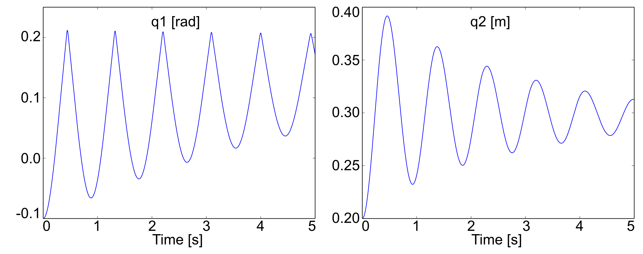
Keeping initial joint angle of 1 [rad] for pendulum leads to an initial position deep in the wall => generating high forces. This might be intractable for the simulation. To avoid this set initial angle at -0.1 [rad].
