Links
A link is used to model a force in the system
It is a point-to-point force element:
A force is applied on the first body and an opposite force is applied on the other body.
The direction of the force is the direction of the line connecting the 2 points.
The intensity must be given by the user.
The hypothesis undelying the link force is that the link element is assumed to be massless. Thus, link forces are useful to model elements for which the mass dynamics can be neglected such the spring damper of a car suspension.
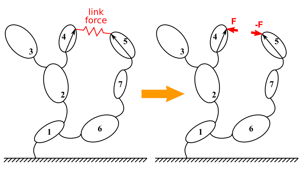
Illustration of the link concept using a potato multibody diagram
The force intensity must be calculated in the user_LinkForces function:
The link length Z and the link velocity Zd are calculated by the symbolic engine and given as arguments of the user_LinkForce function.
The force intensity returned by the user_LinkForce function is automatically projected in the body.
A positive force value represents a link in traction (tends to bring the bodies closer).
A negative force value represents a link in compression (tends to separate the bodies).
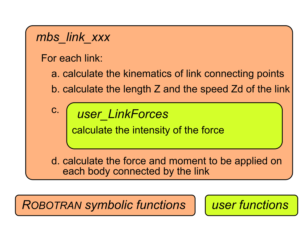
Flow chart of the function call for computing link forces
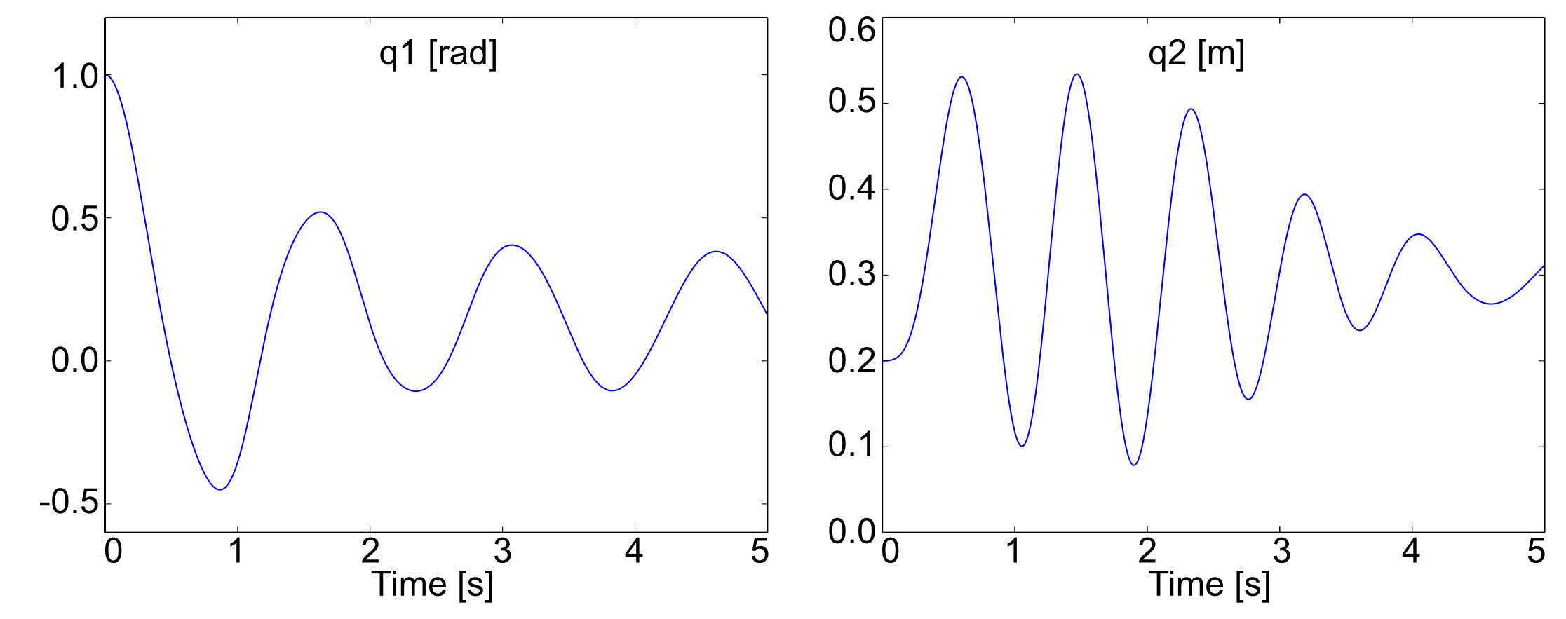
Back to the pendulum-spring example
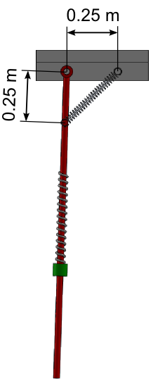
Illustration of the modified example with a link
Add a spring-damper between a point on the base and a point on the pendulum with the following parameters:
Spring stiffness: 100 N/m
Damping: 20 Ns/m
Free length: 0.05 m
Geometry given on the figure, the link is attached to the fixed frame in the X positive direction.
REMARK:
Step 2, 4 and 5 are not impacted by theses function. See the Bodies and joints part for more information
Step 1: Draw your multibody system
Open the Pendulum Spring model in MBsysPad
Add an anchor point on the base and fill the coordinates
Add an anchor point on the pendulum and fill the coordinates
Add the link to the diagram
Click on the Link button in the toolbar
Click on the first point
Click on the second point
Click on the link to edit its properties
Change the name of the link
Add a user model to store the parameter values of the spring damper:
This page explains you how to add a user model for another application, only apply the step 1 and adapt it
Name of the user model : mylink
Parameter K to store the spring stiffness
Parameter C to store the damping
Parameter Z0 to store the free length
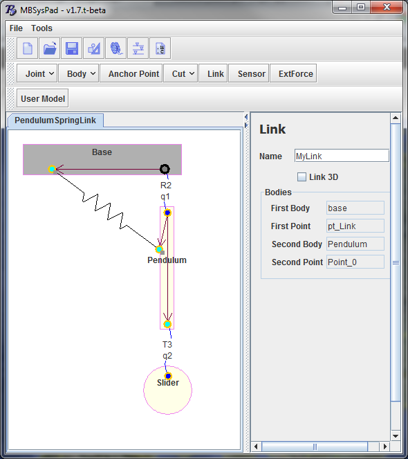
Illustration of the modified example in MBsysPad
Step 2: Generate your multibody equations
Regenerate the multibody equations with the same options as previously.
Step 3: Write your user function
Edit the user_LinkForces function (open the file from the userfctR subfolder of your project)
Write the force equations:
def user_LinkForces(Z, Zd, mbs_data, tsim, identity):
   #...

   # get the link id (see the "tips and trick" if you don't know the get_link_id function")
   L1 = mbs_data.link_id['MyLink']

   if identity == L1:
       K  = mbs_data.user_model['mylink']['K']
       C  = mbs_data.user_model['mylink']['C']
       Z0 = mbs_data.user_model['mylink']['Z0']
       Flink = K*(Z-Z0)+C*Zd

   #...
   return Flink
REMARK:
Sign convention: for a spring system
Flink < 0 ==> compression (Z-Z0 < 0)
Flink > 0 ==> traction (Z-Z0 > 0)
REMARK
If there are several links in the model, all the constitutive laws are introduced in the user_LinkForces function and the if condition is used to distinguish the various links.