Haptic feedback simulator
This tutorial is only for the Robotran team members!
It contains the instructions to use the haptic simulator of UCLouvain/iMMC/MEED laboratory: It is based on several master theses.
NOTE:
This tutorial is based on ROS1.
More info:
This file will explain the different steps to be carried out for using the haptic feedback simulator of the UCLouvain. The purpose of this application is to drive a vehicle (simulated on a computer) with a real steering wheel and pedals and receive the torque feedback back in the steering wheel in order to create a realistic driving-simulator.
First there is a small introduction and explication on the functioning of the simulator.
Then there will be some informations on installing and using the following software:
- Robotran: this software takes care about the simulation of a multi-body model (for this application it will be a kart, a car, …)
- ROS: this software is used to carry on the communication between the different devices.
Then some instructions on how to install and compile the ros_rob package on your computer.
After that the tutorial will show you how to connect your computer to the Raspberry used for the simulator.
The next step explains to you how to turn on the servo-drive and servo-motor of the simulator and how to launch and use the application.
Finally, the last part explains how to add its own multi-body vehicle model into the application.
Note: The simulator works on the lab’s PC with which everything is functional but it is possible to use your own computer (ideally running Linux Ubuntu, the example here is done with Ubuntu 20.04.4 LTS).
Introduction
Here is a presentation of the haptic feedback simulator:
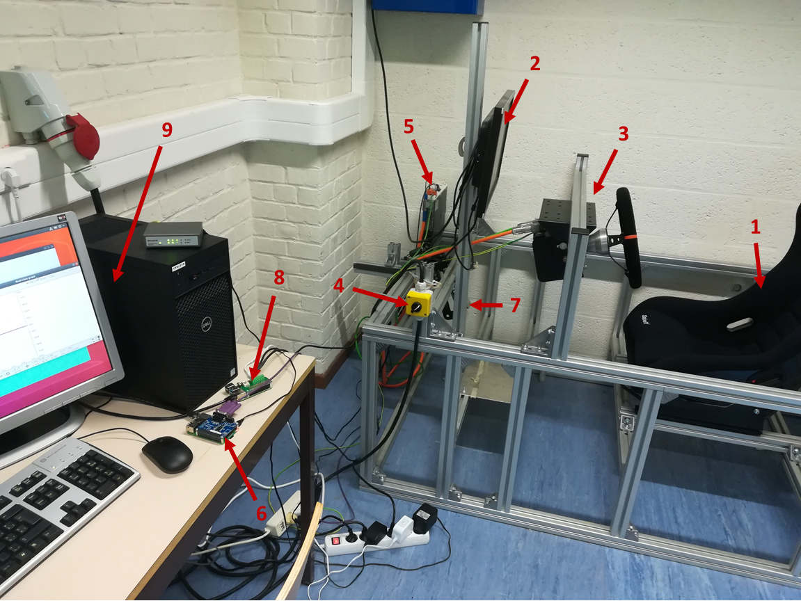
HIL simulator
With:
- A seat.
- A screen displaying a graphical interface of the simulation of the vehicle.
- A steering wheel connected to a servo-motor.
- A switch to turn on/off the servo-motor.
- A servo-drive used for the communication between the servo-motor and the Raspberry Pi3B+.
- A Raspberry Pi3B+ with a PiCAN2 used for the communication between the servo-drive and the computer.
- Two pedals connected to potentiometers.
- A Raspberry Pi4B with an ADC used for the communication between the potentiometers and the computer.
- A computer running the simulation of the vehicle.
The different steps of communication are the following:
- The driver steers the car by using:
- The steering wheel
- The pedals
- Data are retrieved:
- A coder included in the servo-motor measures the position and velocity of the steering wheel and sends those data to the Raspberry Pi3B+ through a CANopen protocol of communication.
- Potentiometers measure the positions of the pedals and send those data to the Raspberry Pi4B via I²C.
- The Raspberry’s receive the data and send it to the software Robotran (running on the computer) through a ROS protocol of communication (called topic).
- Robotran, which is simulating the dynamics of a vehicle, use the data
to:
- Steer the vehicle and compute the torque feedback in the steering wheel.
- Modify the acceleration / braking of the vehicle.
- It returns the value of the torque to the Raspberry Pi3B+ through ROS communication. Then this latter sends a CANopen command to the servo-drive which set the computed torque into the servo-motor.
The driver is now able to steer the vehicle and feel the torque feedback.
Hardware architecture
The following diagram shows the various hardware components, the
physical connections between them as well as their necessary power
supply: 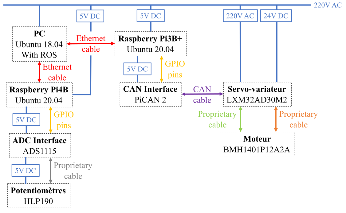
Installation and configuration
Ros and Robotran
Please install and configure Robotran and ROS following this tutorial.
ros_rob package
Please follow this tutorial.
Setup the communication Raspberry-computer
In this application, 2 Raspberry’s are used: the first to have CANopen communication capability (with an extension PiCAN2 fixed on the GPIO pins of the Raspberry) and the second to have an I²C connexion with the potentiometers. In order to use the strengths of the ROS communication, we need to create a complete, bi-directional connectivity between the Raspberry’s and the computer.
SSH communication
Please follow this tutorial.
Ensure that the Ethernet cables are connected to the router. You must have 1 cable for the PC and one for each Raspberry.
ROS across multiple machines
Please follow this tutorial.
Setup the hardware and use of the haptic feedback simulator
This section shows you how to connect your computer to the simulator and turn on the different devices. Next we will see how to launch a simulation.
Setup the devices
- As explained in a previous section, you must connect the Ethernet cables of the Raspberry’s to router, himself connected to the port of the computer.
- Turn on the Raspberry’s by plugging them in. You will have to wait a few seconds (the time they boot).
- Check that the cable for the CAN communication (the purple one) is connected to PiCAN2 of the Raspberry Pi3B+.
- Check that the cables of the potentiometers are well connected to the ADC card of the Raspberry Pi4B.
- Turn on on the screen and connect it to the computer.
- Plug the cable for the ground.
- Turn on the servo drive by plugging it.
- Plug the servo-motor power and then turn on the rotary switch. At this time the power stage (= the servo-motor) is not yet enabled, it will be done by CAN communication during the running of the code. The message “rdy” (for “ready”) is displayed on the servo-drive screen.
Launch the simulation
First, open a terminal on the computer and enable the ROS environment with:
labo@PCxxx:~$ roscore
After that, open a second terminal on the computer and connect it to the first Raspberry with:
labo@PCxxx:~$ ssh steerhaptic@192.168.100.5
Once connected, you can run the first node to enable the servo-drive:
steerhaptic@192.168.100.5:~$ rosrun ros_rasp lexium32A_CANopen
Then, open a third terminal on the computer and connect it to the second Raspberry with:
labo@PCxxx:~$ ssh pedalhaptic@192.168.100.6
You can now run the second node:
pedalhaptic@192.168.100.6:~$ rosrun ros_rasp2 talker_pedals
At this point, you should view this line on the two terminals connected to the Raspberry’s:
Running ...
Finally open a fourth terminal and launch the application with:
labo@PCxxx:~$ roslaunch ros_rob haptic_simulator.launch
So you have three main terminals:
- One for the ROS node on the Raspberry
steerhaptic: it takes care about the CAN communication with the servo-drive and displays all the informations of the servo-drive settings. - One for the ROS node on the Raspberry
pedalhaptic: it takes care about the I²C communication with the pedals and displays the state of the corresponding node. - One for the two ROS nodes on the Laptop: one node runs the Robotran simulation and the second creates some interactions with the user for the simulation as shown here below.
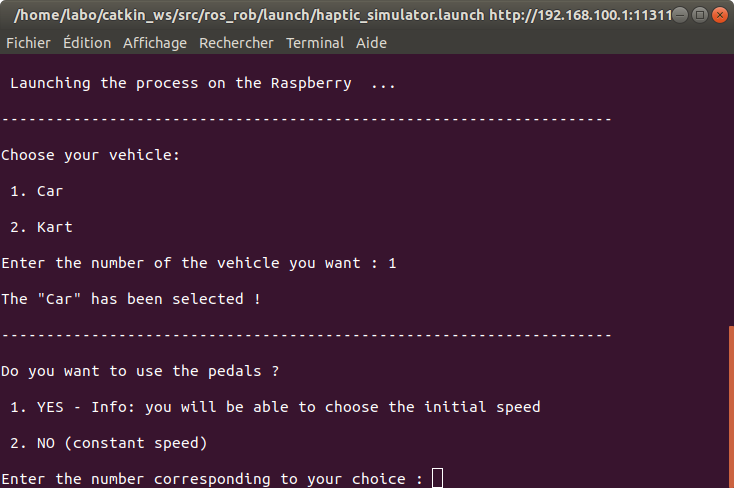
Choice of the parameters
Now you can choose the different parameters of the simulation ! You just have to type the number corresponding to your choice in the terminal and press “enter”.
- Vehicle:
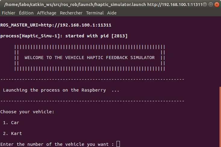
- The car

- The kart
- The car
- Pedals mode:
- Simulation / Circuit:
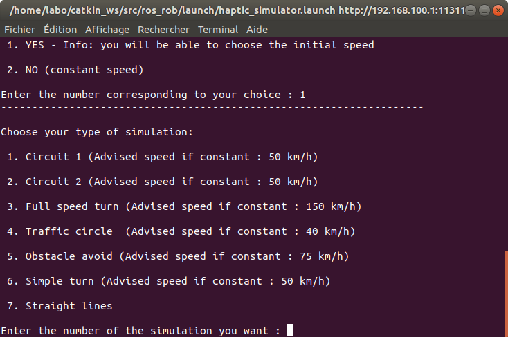
- Circuit 1

- Circuit 2

- Full speed turn (not available with the kart): drive at high speed then turn and feel the augmentation of the torque in the steering wheel. Simulation done with random mechanic trail.
- Traffic circle (not available with the kart): take a traffic circle at constant speed. At a random time, the ground will be sliding during 2.5 seconds, try to stay on the traffic circle ! Simulation done with a random mechanic trail.
- Obstacle avoid (not available with the kart): drive on a straight road a constant speed. An obstacle is placed at a random distance, try to avoid it ! Simulation done with random mechanic trail. The “inside view” is advised.
- Simple turn (not available with the kart): take this simple turn
at different speed and feel the difference…

- Straight lines (not available with the kart): useful to visualize
the speed and try the pedals !

- Circuit 1
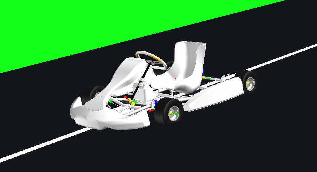
- View choice (not available with the kart):
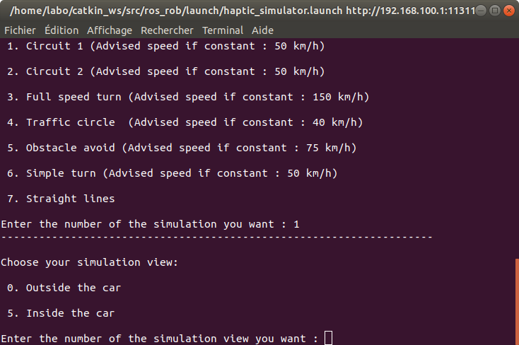
- The kart view

- The car outside view

- The car inside view
- The kart view
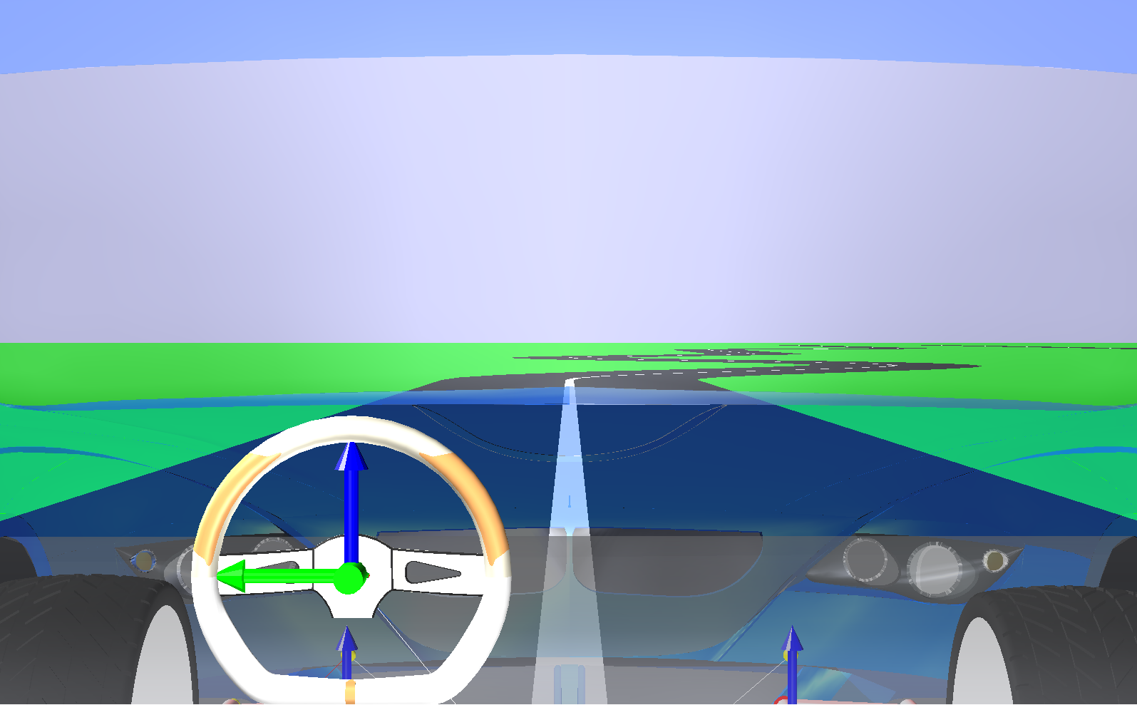
- Initial speed:
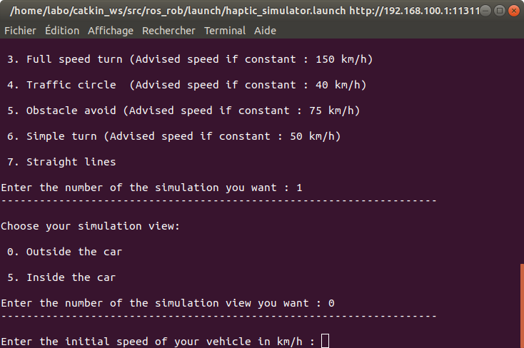
Press enter and the simulation should run !
At the end, close the nodes, the Raspberry’s, and don’t forget to unplug everything.
Include your own Robotran project
Please follow this tutorial.
In step 5, you can use the template main_robotran_template_haptic_simulator.cpp and follow the change instructions inside the template.
In step 6, for the haptic simulator, you need to put the following function in the user_DrivenJoints function (only for direct dynamics):
(*mbs_data->user_model->thread.thread_struct->pointeur_give_pos_vit_access)();
And the following one in the user_dirdyn_loop function:
( (*mbs_data->user_model->thread.thread_struct->pointeur_give_torque_access)();
NOTE:
Take care about the sign of the torque, position and velocity of your steering wheel in Robotran and be sure they match the position, velocity and torque of the really steering wheel.
Known troubleshootings
Here is a list of tips for some issues that may arise:
You can stop the motor at anytime by pressing “CTRL+C” in the Raspberry’s terminal or by turning off the rotary switch.
It may happen that the Raspberry does not start correctly after a modification of its ROS packages. To correct this, please read the Installation and compilation of KaCanOpen section in the CAN-develop branch of the ros_rasp package.
To automate the application, the ROS parameters are used. It can happen that certain parameters are not detected and that the code remains blocked in a while loop. You can change the value of a parameter with the following command line:
$ rosparam set *name_of_parameter* *value_of_parameter*The parameter robotran_simu_run is set to 1 during a Robotran simulation and to 0 when the simulation is finish.
The parameter choice_done is set to 1 when the choice to make a new simulation or not is done, and to 0 otherwise.
The parameter restart_robotran is set to 1 when the choice to make a new simulation is done, and to 0 otherwise.
The parameter haptic_ready is set to 1 when the servo drive is correctly set to launch a simulation, and to 0 otherwise.
So in case of problem, have look on the terminals (or the code) to see where the application is stopped and set manually the parameters to unlock it.
That’s it folks ;-)